
MFFAFP Filter Profile File GOCA Configuration
The abbreviation MFF stands for Mixed Format Filter. MFF input and output filters are part of the MFF architecture and, as part of DocBridge Core, support the processing steps in the DocBridge products. Some filters read files of different formats, others are write files into the respective output format. In some cases, a format is supported on input and output side.
Filters are configured in profile XML files with the file extension .pro. In these profiles, you may specify where specific resources like fonts are to be searched, the code pages to be used or the mapping of font names to font files. When a format is supported on input and output side, like AFP, input and output processing is configured in the same profile file.
The following information focuses on GOCA. GOCA is short for Graphics Object Content Architecture. It is an architecture that provides a collection of graphics values and control structures used to interchange and present graphics data.
GOCA drawing orders are used to present vector graphics in AFP pages, page segments, or overlays. The GOCA architecture defines two levels, Drawing Level 2 Version 0 (DR/2V0) and Graphics Subset Level 3 (GRS3).
Whether the AFP data contains DR/2V0 or GRS3 generally depends on the device used to print it. To ensure the AFP filter produces the expected output, the GOCA configuration settings in the MFFAFP filter profile should be verified and adjusted when needed.
The input section of the MFFAFP filter profile file contains the following GOCA related elements:
1. gocarasterimageresolution:
Each image point is mapped to a pixel of the output device. In the absence of image resolution information, a printer dependant resolution is used. You can adjust the size of the GOCA image by specifying gocarasterimageresolution. If the value 0 (default) is specified, the MFFAFP filter uses the resolution of the input document.
<gocarasterimageresolution value="0"/>
2. GocaLineWidthBase:
All GOCA line widths are defined as a factor to be multiplied with the normal line width. Graphics Subset Level 3 (GRS3) specifies a default normal line width value of 0.01 inch, but with Drawing Level 2 Version 0 (DR/2V0) the value is device-dependent. If lines are thicker or thinner than expected, the normal line width of the device is not 0.01 inch. You use GocaLineWidthBase to specify the printer specific value.
<GocaLineWidthBase value="0.01 in"/>
3. GocaLineJoinStyle:
The default style for the shape used to join lines with Graphics Subset Level 3 (GRS3) is "round ", but with Drawing Level 2 Version 0 (DR/2V0) the default style is device specific. If the default used by the device is not "round" (default), you use GocaLineJoinStyle to set one of the other supported values: "miter" or "bevel". See samples below:
<GocaLineJoinStyle value="round"/>
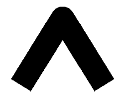
round

miter

bevel
4. GocaLineCapStyle:
As with the line join style, the default line cap style is not defined by theDrawing Level 2 Version 0 (DR/2V0) specification. The line cap shape used when no explicit value is set in the input data, depend on the device. The default style defined with Graphics Subset Level 3 (GRS3) is round. If the default style used by the device is not "round" (default), use GocaLineCapStyle to set one of the other supported values: "butt" (or "flat") or "square". See samples below:
<GocaLineCapStyle value="round"/>

round

butt

square
5. gocaprocessrefcsys05:
The element provides the possibility to process files with deprecated coordinate system references in the same manner as older printers. GOCA objects can be placed inside text with an IOB (Include Object) structured field. By default deprecated 0x05 "current text (I,B) coordinate system" "RefCSys" values are ignored. If gocaprocessrefcsys05 is set to "true", RefCSys 0x05 is interpreted and the reference coordinate system set to "current text (I,B)".
<gocaprocessrefcsys05 value="false"/>
Ask Compart support for the "GOCA configuration sheet" test file if you are not sure about your devices' default line settings.
